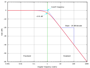
Frequency response requirements differ depending on the application. In high fidelity audio, an amplifier requires a frequency response of at least 20–20,000 Hz, with a tolerance as tight as ±0.1 dB in the mid-range frequencies around 1000 Hz, however, in telephony, a frequency response of 400–4,000 Hz, with a tolerance of ±1 dB is sufficient for intelligibility of speech.
Frequency response curves are often used to indicate the accuracy of electronic components or system. When a system or component reproduces all desired input signals with no emphasis or attenuation of a particular frequency band, the system or component is said to be "flat", or to have a flat frequency response curve.
The frequency response is typically characterized by the magnitude of the system's response, measured in decibels (dB), and the phase, measured in radians, versus frequency. The frequency response of a system can be measured by applying a test signal, for example:
- applying an impulse to the system and measuring its response (see impulse response)
- sweeping a constant-amplitude pure tone through the bandwidth of interest and measuring the output level and phase shift relative to the input
- applying a signal with a wide frequency spectrum (for example digitally-generated maximum length sequence noise, or analog filtered white noise equivalent, like pink noise), and calculating the impulse response by deconvolution of this input signal and the output signal of the system.
Once a frequency response has been measured (e.g., as an impulse response), providing the system is linear and time-invariant, its characteristic can be approximated with arbitrary accuracy by a digital filter. Similarly, if a system is demonstrated to have a poor frequency response, a digital or analog filter can be applied to the signals prior to their reproduction to compensate for these deficiencies.
Frequency response measurements can be used directly to quantify system performance and design control systems. However, frequency response analysis is not suggested if the system has slow dynamics.

No hay comentarios:
Publicar un comentario